measure something: add a sensor to a microcontroller board that you have designed and read it
I designed my board with an Atmega 328p processor using Eagle software.

After producing the board, as we did in the previous week of electrical production.

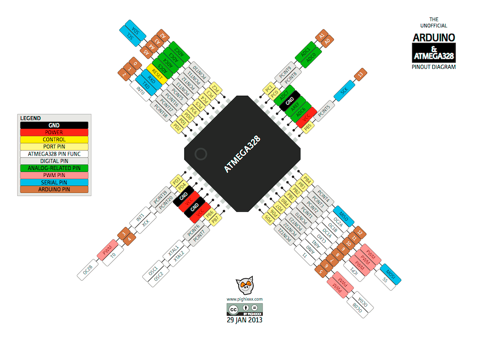
ATmega328_Pinout I'll use it to help me connect the pieces I want to work on.< br>
Sensor
It emits an ultrasound at 40 000 Hz which travels through the air and if there is an object or obstacle on its path it will bounce back to the module. Considering the travel time and the speed of the sound you can calculate the distance.

The ultrasound unit HC-SR04 includes 4 pins, Ground, VCC, Trig and Echo. Ground screws, unit VCC pins should be grounded, 5-volt pins on the Arduino board respectively. you need to select Trig and Echo pins. In this case they are pins 9 and 10 on the Arduino board and they are called trigPin and echoPin. Then you need a long variable, called the "duration" of the travel time that you will get from the sensor and a valid distance variable.
In setup you should define trigPin as output and echoPin as input as well as initiate a serial connection to display results on the serial monitor.

After writing the code, this is the result
LDR
LDR (Light Dependent Resistor, or Photo resistor) is basically a resistor that change resistance depending on light. More light means less resistance. Less light means more resistance.

This graphic will take an analog voltage reading and use this to determine the brightness of the red LED. The darker it is, The brighter the LED. LED must be connected to a PWM pin in order to work.
Connect +5V of the Arduino to one pin of the LDR (LDR pins can be swapped, so no worries about polarity here).
Connect the other pin of the LDR to A0 (analog pin of the Arduino) and one pin of the 100KΩ resistor.
Connect the other pin of the 100KΩ resistor to GND of the Arduino.

After writing the code

After writing the code, this is the result
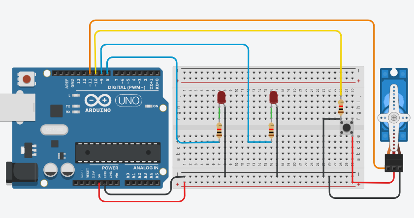
I will connect the servo motor and 2 LEDS and Button To the board, this image is to illustrate how to connect the components
Button Pushbuttons or switches connect two points in a circuit when you press them.
I have written the code when I press the button, the machine starts from zero until the time it is intended to run.
A boolean holds one of two values, true or false. (Each boolean variable occupies one byte of memory.)
-Attach the Servo variable to a pin.
-pinMode(LED, OUTPUT);
-In the program, pin ---, which has LED connected to it, is set up as output in the setup function.
-In the main loop, the state of the buttonPin is saved in the variable ButtonState.
-If (previousButtonState! = ButtonState && buttonState == HIGH) {myservoEnabled =! myservoEnabled;}
If the previous button is equal to buttonState, which means buttonState is equal to HIGH (as if I pressed the button), and if the condition statement is met, reset the myservoEnabled to zero.
-if (myservoEnabled == 1) { digitalWrite (LED, HIGH); digitalWrite (LED1, LOW); myservo.write (0); delay (10000); myservo.write (180);delay (150)
If the servo motor works, turn on the led, turn off the led1, and move the servo motor from angle 180 after a period of time to angle 0 over a period of time.
-else {digitalWrite (LED, LOW);digitalWrite (LED1, HIGH);myservo.write (0); ;}
If the servo motor does not work, turn off the LED, turn on LED1, and move the servo motor to angle 0
-previousButtonState = buttonState;
Means the previous button is equal to the button state
.PNG)
I made two wires instead of a button, because I do not currently have them, but it worked as shown in the video below:
This is the site for group assignments:Press here
This is the code file: